DC Motor Feedback Analysis: Block Diagram, SFG & Transfer Function
Автор: Razmer Rezwan
Загружено: 2026-01-15
Просмотров: 13
In this video, I’ll guide you through the process of modeling a DC motor control system, starting from the circuit equations and deriving the transfer function. The video will cover:
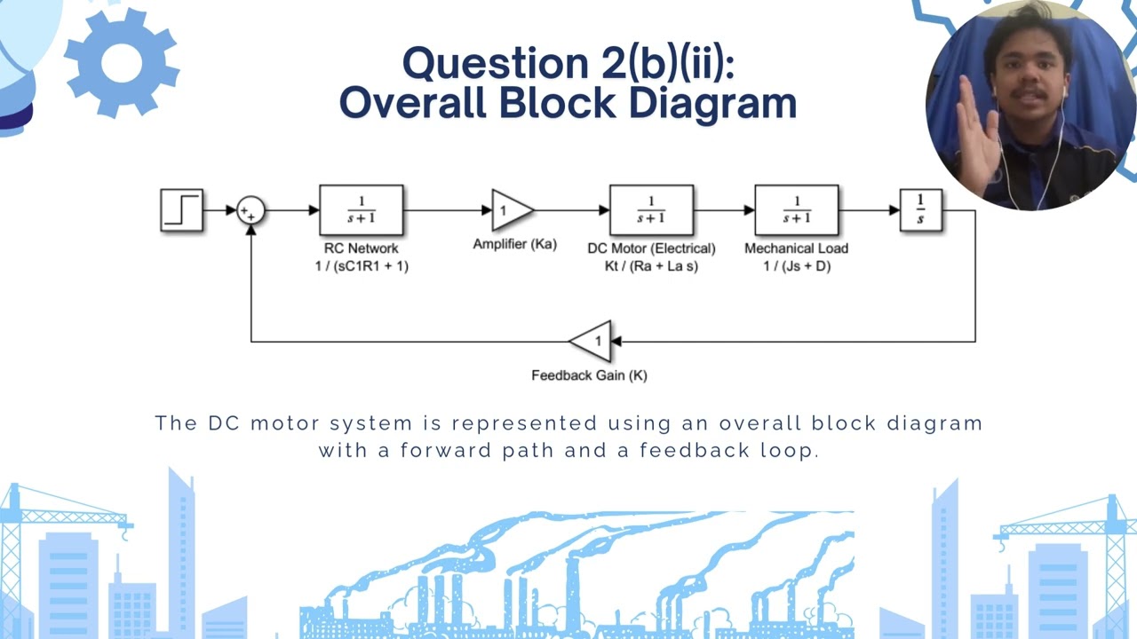
• Circuit Equations: I’ll explain the key electrical and mechanical components of the DC motor system, including the amplifier, armature, back-EMF, torque constant, inertia, and load.
• Transfer Function Derivation: I’ll show how to transform the circuit equations into a transfer function G(s), representing the relationship between input and output.
• Step-by-Step Modeling: I’ll break down the system into subsystems (amplifier, armature, torque generation, mechanical load) and explain how to combine them into a simplified transfer function for the overall system.
This video provides a comprehensive approach to modeling DC motor control systems, with clear explanations on how to use Laplace transforms and basic control system techniques.
Доступные форматы для скачивания:
Скачать видео mp4
-
Информация по загрузке:


