LDM
Автор: Le labo de Michel
Загружено: 2025-03-07
Просмотров: 7602
This video shows detailed functioning of the power supply and analog to digital converter of the accelerometers.
00:00 - Intro
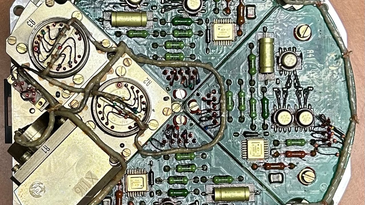
00:07 - Electronic boards overview
01:37 - Step-down DC_DC converter
02:26 - Auto-oscillant DC-DC converter
03:51 - Multislope ADC
05:10 - Multislope ADC - Schematic diagram
07:51 - Multislope ADC - Digital circuits
08:49 - Multislope ADC - How it works
10:32 - Multislope ADC - first test
Power supply:
A first step-down converter converts a voltage of 25-30V coming from the battery assembly to a regulated voltage of 20V.
A second DC-DC converter delivers 3 galvanically isolated voltages for each accelerometer assembly.
+/-15V for the electronic circuits and the accelerometer itself
+5V for the digital circuit
+15V for the floating voltage reference
The power supply board comprises also the current power supply for the LED used for the zero detector of ЦЕ1940-1/ЦЕ1940-1M accelerometer. P/S board with date code 2024 has a more complex LED current source than the P/S board with data code 2022. Modifications are done manually.
ADC board:
The ADC is of the multislope type. There are two outputs which delivers short pulse at the beginning of each positive-going ramp for one and at the beginning of each negative-going ramp for the second. The outputs are galvanically isolated using small pulse transformers and are fed to the guidance computer using two pairs of twisted wires. The ADC is not complete, the measurement computation is performed on the guidance computer side.
Schematic diagram:
https://mwblog.fr/wp-content/uploads/...
Доступные форматы для скачивания:
Скачать видео mp4
-
Информация по загрузке:


