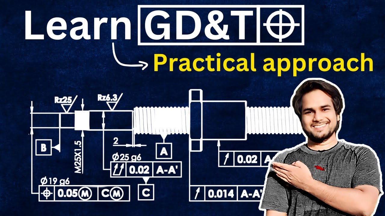
7 Main Reason to Make Drawings in GD&T | Mechanical Design Engineers must Know
Автор: Master Mechanical DESIGN
Загружено: 2024-04-30
Просмотров: 14863
In this video I have explained why a mechanical design engineer should always prefer GD&T (Geomatic dimensioning and tolerancing) method to make manufacturing drawings for mechanical parts, instead traditional coordinate direct dimensioning method, I have explained main 7 reasons, 7 main disadvantages, shortcoming of traditional coordinate direct dimensioning method in following chapters.
Chapters:
00:00 How to make habit of GD&T
04:00 Reason 01- GD&T Geometry form control
07:52 Reason 02- GD&T Profile control
10:35 Reason 03- Square and GD&T Cylindrical Tolerance zone
17:04 Reason 04 -Accumulation of tolerance, GD&T Basic Dim.
19:26 Reason 05- Fixed and at MMC tolerance zone
24:24 Reason 06- GD&T Measuring setup
28:17 Reason 07- GD&T Measurement reference
29:40 Conclusion
Copyright Disclaimer: Master Mechanical DESIGN is an educational channel, Provides Industrial Machine design related education, and sometimes we use clips and images from website like Pexels, pixabay and YouTube clips to explain about the machine design, But all under section 107 of the copyright Act 1976, allowance is made for FAIR USE for purpose such as criticism, comment, news reporting, teaching, scholarship and research.
#gd&t #drawing
#mechanicaldesign #designenginner #Machinedesign #Mechanical #Solidworktutorial #Mechanicalengineering #mastermechanicaldesign #solidworkstutorialformechanicalengineering
GD&T drawing tutorials
GD&T drawing exercises
GD&T drawing step by step
how to become mechanical design engineer
solidworks tutorial for mechanical engineering
how to become a successful mechanical engineer
how to get high salary jobs in mechanical engineering

Доступные форматы для скачивания:
Скачать видео mp4
-
Информация по загрузке:


![Everything about GD&T Rule 1 and Rule 2 [YOU DON'T KNOW]](https://imager.clipsaver.ru/bGnXA1c_RZM/max.jpg)