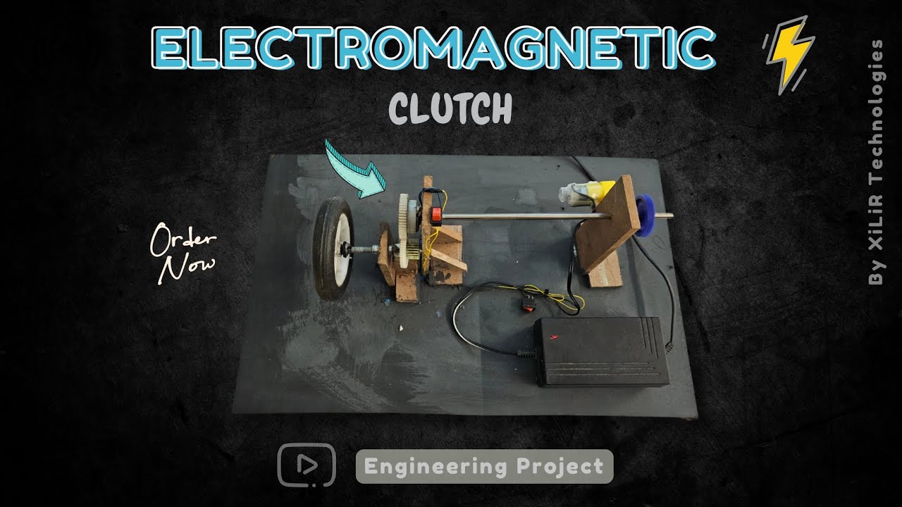
⚙️ Electromagnetic Clutch System Project | Mechanical Engineering
Автор: XiLiR Technologies
Загружено: 2024-10-01
Просмотров: 466
#electromagnetic #project #ideas
#engineeringproject #capstone Project #major Project
for EEE ECE Mechanical Science Exhibition project
To Buy/ Make this project with training
contact us:
👨🏼🏭𝗩𝗶𝗽𝗶𝗻 𝗞𝘂𝗺𝗮𝗿 𝗦𝗵𝗮𝗿𝗺𝗮
Ph.D., M.Tech, B.Tech in ECE
🎓Lecturer 🚀#Researcher #Drone #Robotics
Whatsapp : https://wa.me/919810326343
https://xilirprojects.com/product/ele...
https://xilirprojects.com
1. Synopsis/ Documents
2. Block diagram and circuit diagram with explanation.
3. Bill of material.
4. Components Specification list
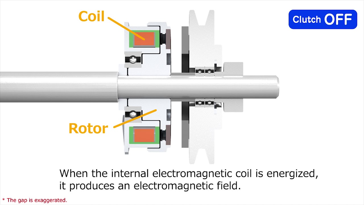
5. Working principle of the project.
6. Datasheet of all components.
7. Program/code of Arduino with training.
8. Complete Working principle description.
9. Complete interfacing description.
10. you can get the project by courier.
11. viva preparation
ask us if other things needed.
Description
The Electromagnetic Clutch system features a 12V high-speed motor connected to a 12V inverter via a switch. When the switch is pressed, the motor rotates and drives a set of gears mounted on a central shaft. The shaft connects to a clutch system with another DC motor. Engaging the clutch motor allows proper wheel movement, while disengaging the clutch acts as a brake, halting the wheel movement when the switch is turned off.
Objectives
• To utilize a gear system aligned with a central shaft to effectively transfer rotational power from the motor to the wheels, ensuring smooth and reliable movement.
• To implement a clutch system with an additional DC motor to manage the engagement and disengagement of gears. This allows for controlled wheel movement when engaged and braking functionality when disengaged.
• To provide braking capability by disengaging the clutch when the switch is turned off, effectively stopping the wheel movement and ensuring safety and control.
• To enable precise control of the 12V high-speed motor's operation through a switch, allowing the motor to start and stop based on user input.
Components required
12V inverter
Gears X4
Shaft
Wheels X2
Switches X2
Connecting wires
Block diagram
Methodology
The project has a 12V high RPM motor connected to a 12V inverter through a switch. When the switch is pressed, the motor starts rotating. This motor is coupled with gears that are aligned at a height, mounted on a central shaft. The shaft's other end is connected to a clutch system. This clutch system includes an additional DC motor, which is integrated into the gear mechanism. When the switch is pressed, the clutch motor engages, allowing the gears to turn and enabling proper wheel movement. This setup facilitates the desired motion of the wheels, controlled by the rotational power from the high-speed motor and the engagement of the clutch system. When the switch is turned off, the clutch acts as a brake. This disengagement stops the gears from rotating, thereby halting the movement of the wheels and providing braking functionality. Many features related to IOT like automatic calculation of RPM and automatic break through a sensor can also be implemented.
Electromagnetic clutch system project, electromagnetic clutch working, electromagnetic clutch design, clutch system project, automotive clutch system, electromagnetic clutch mechanism, clutch system for vehicles, electromagnetic clutch engineering project, automotive clutch technology, electromagnetic clutch components, electromagnetic clutch diagram, electromagnetic clutch application, automotive projects,
JOIN US GUYS THANKS
========
👥Facebook: / xilirprojects
🐤Twitter: / xilirprojects
✅🔥Follow us on 📸Instagram🔥✅
/ xilirprojects
👨🏻🎓Linkedin: https://bit.ly/39occm2
========
𝗔𝗯𝗼𝘂𝘁 𝗨𝘀 :
𝗫𝗶𝗟𝗶𝗥 𝗧𝗲𝗰𝗵𝗻𝗼𝗹𝗼𝗴𝗶𝗲𝘀™ is India’s 🔖Top rated & Leading R&D Company. It's an ISO 9001:2008 Certified Company & Govt Approved under MCA & it was Established in 2013.
Доступные форматы для скачивания:
Скачать видео mp4
-
Информация по загрузке: