Use Buck Converter Xl4016 As a Lab Power Supply | 1.5V to 30V | 0.2 - 12A | 300W High Power
Автор: Creative for you
Загружено: 2021-01-08
Просмотров: 104136
hello Friends in this vidoe i will show how to Use a Xl4016 As a power supply....
The XL4016 module is based on the XL4016 integrated circuit. Here is the first general description paragraph from the data sheet. "the XL4016 is a 180 kHz fixed frequency PWM buck (step-down) DC/DC converter, capable of driving a 8A load with high efficienc, low ripple and excellent line and load regulation
.The short Circuit current can go much as 12A the voltage is adjustable from 1.2 v to 32V maximum input is 36V in my video i used a 25v 2A transformer sorry about that
About Module
Regulator Type:
Step Down
( Non Isolated input to Output
Input Voltage:+7 to 32vdc
Output Voltage:+0.8 to 28vdc
Output Current:12A Rated
,( 8A maximum with heat sink )
Adjustable Current:0.2 to 12A
Efficiency:Up to 95%
( when output voltage is set high )Protection:
Short circuit current limiting, thermal shutdown


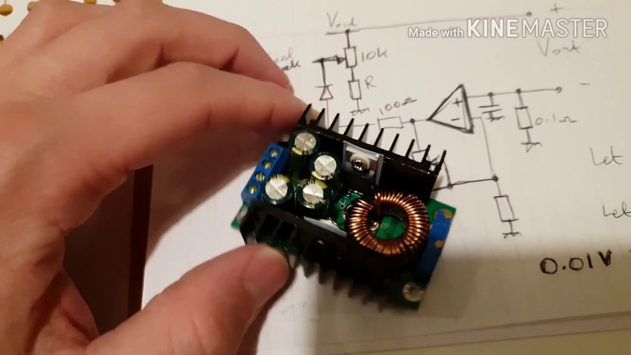
The way it works is this:
The pot is a variable resistance and is connected between OUT+ and Feedback. There is another (fixed) resistor between Feedback and Ground.
"Feedback" is the negative input of an operational amplifier. The positive input of that operational amplifier is connected to a reference voltage, which varies from one design to another but is usually between 0.8 Volts and 1.25 Volts. The XL4016 and SZBK07 are both about 1.2 volts.
These components form a negative feedback control loop that maintains the Feedback pin at the reference voltage. If the voltage at OUT+ is too high, the output of the operational amplifer goes down and decreases the PWM duty cycle of the converter, which decreases the output voltage. The converse happens if the OUT+ voltage is too low. Winding the voltage control pot one way to reduce its resistance reduces the output voltage; winding it the other way to increase its resistance increases the output voltage.
It is essential to have this feedback control loop formed by the pot, a resistor to ground, and the operational amplifier.
However if the pot is wound up to a high value, additional current from another source can be fed into the Feedback pin, which has the effect of reducing the output voltage.
One way of providing that additional current is by putting an external pot between OUT+ and the Feedback pin. Using a suitable value pot will give a new (lower) maximum setting for the OUT+.
Another way of providing additional current is to connect a resistor and diode coming from a PWM pin of a microcontroller. The resistor is needed to avoid drawing excessive current from the PWM pin. The diode is needed to ensure that the current is always additional.
1 to 30V, 10V, 12V to 30V, 14V, 15v, 16v, 1v to 30V, 25V, 2V, 30V, 3V, 5V, 6V, 7v, 8V, 9V, DIY lab power supply, Diy, How to make power supply, adjustable power supply, boost, diy power supply, inverter, inverter 12V, lab power supply, lab power supply diy, power supply, power supply unit, powersupply, simple 1-30V, simple oscillator, simple power supply, voltage booster, boost converter, variable power supply, adjustable voltage, 5v power supply, lab power unit, voltage range
#powersource #SMPS #buckconverter #adjustablepowersupply
#DIY lab power supply
#powersupply

Доступные форматы для скачивания:
Скачать видео mp4
-
Информация по загрузке: