Digital logic #7: Combinational logic including the encoder, decoder, and multiplexer
Автор: Aaron Dahlen
Загружено: 2021-02-21
Просмотров: 19339
Summary:
This lecture extends combinational logic with encoders, decoders, and multiplexers as practical building blocks. Concrete examples include a compass-driven encoder, a three-to-eight decoder, and several 4-to-1 multiplexer realizations. The session closes by introducing Karnaugh maps for simplifying sum-of-minterms logic expressions.
Why This Matters:
Encoders, decoders, and multiplexers appear throughout datapaths, display interfaces, and processor bus interconnects. Understanding their gate-level structure supports confident schematic design and more readable hardware descriptions later. Karnaugh maps provide a systematic way to reduce equations before committing to hardware implementations.
Content covered in the video:
Overview of multi-input, multi-output combinational logic, including the seven-segment display driver with 4-bit hexadecimal input and seven outputs
Design motivation for encoders using an eight-direction compass, mapping D0–D7 signals into a compact three-bit code CBA to reduce wiring
Three-to-eight decoder design using complemented inputs, three-input AND gates, and one-hot outputs D0 through D7
Truth table interpretation of the decoder behavior, highlighting the mapping between 3-bit inputs and single asserted data lines
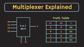
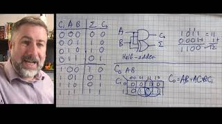
4-to-1 mux viewed as a controlled switch, its truth table, AND-OR implementation, and scaling to 8-input and 8×8 bus-based multiplexers
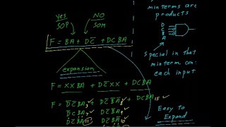
Introduction to Karnaugh maps: cell labeling with Gray code ordering, minterm placement, implicant grouping, and recovering the simplified b̅ function

Доступные форматы для скачивания:
Скачать видео mp4
-
Информация по загрузке: