Multi-view drawings
Автор: CAD Training Now
Загружено: 2012-08-22
Просмотров: 28541
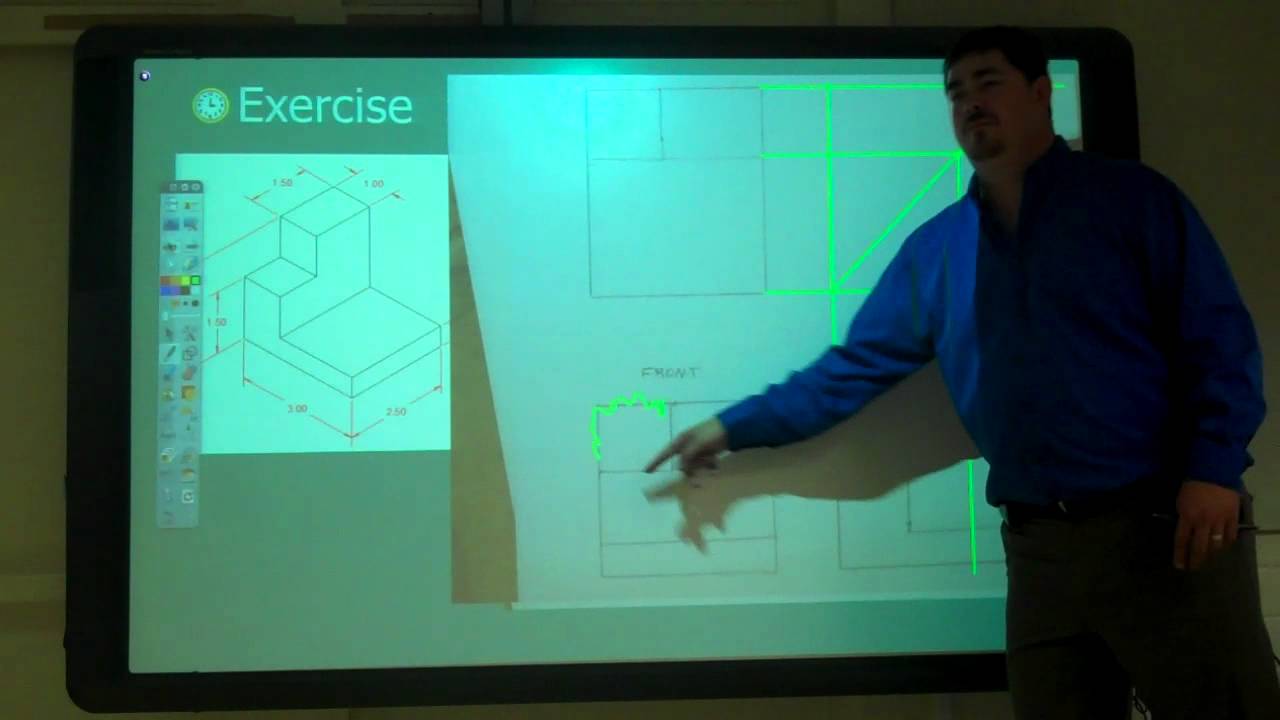
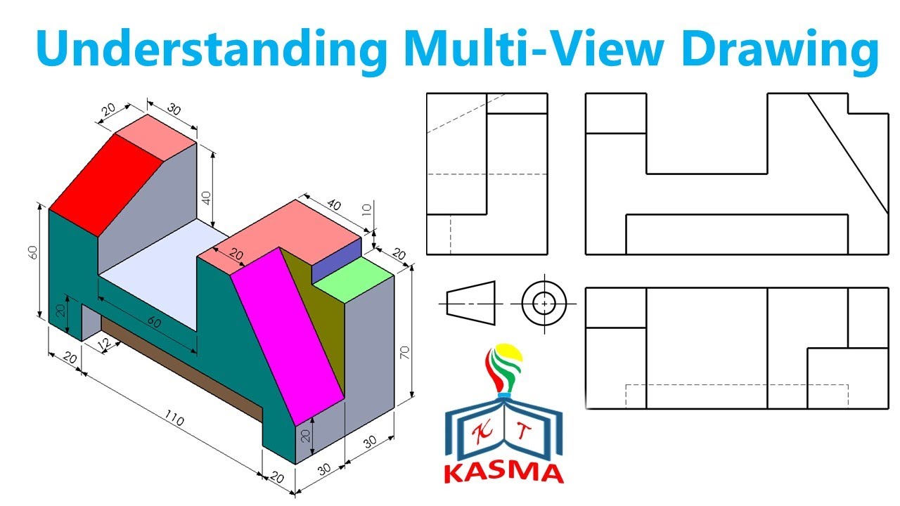
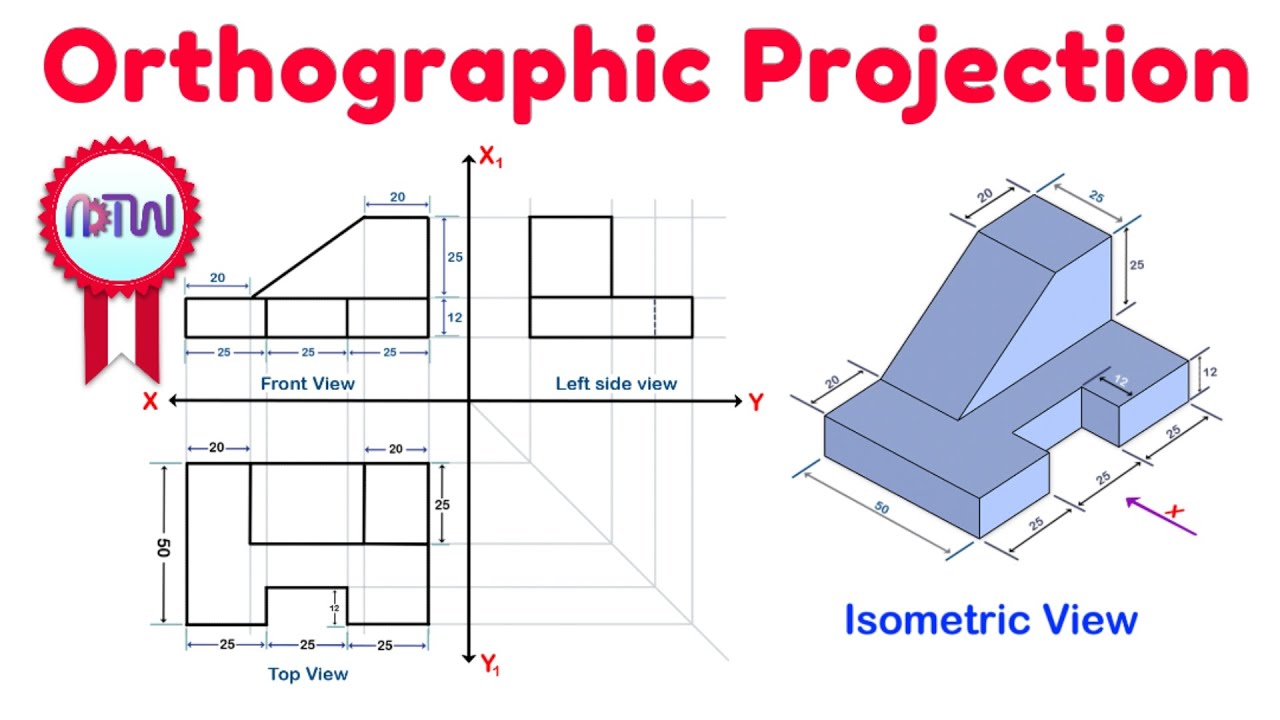
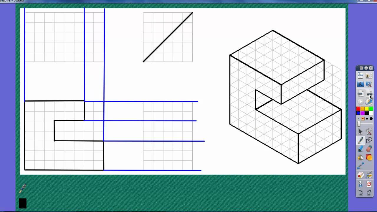
In this video, I dive into multi-view drawings, which are the standard way to represent a 3D part in 2D for manufacturing. The key to creating these drawings is understanding how to select and arrange your views. I begin by explaining that the front view should always be the most descriptive view of the part's overall shape, using a car as an example where the side view is more descriptive than the actual front. I then stress the importance of using the least number of views possible to fully describe the object. I demonstrate the projection rules, emphasizing that every corner must be projected to the adjacent view, and introduce the miter line (a 45-degree line) as a crucial tool for accurately transferring the depth measurement between the top and side views. I also introduce hidden lines (dashed lines) to represent features that cannot be seen from a particular view, and walk through two detailed examples to solidify the entire process of drawing complete, accurate multi-view projections.
Video Chapters
[00:00] Review of Projection Methods
[00:45] Picking the Front View (The most descriptive view)
[02:08] Using the Least Amount of Views to Describe the Part
[03:12] Introduction to Hidden Lines (Dashed lines)
[04:30] Step-by-Step Guidelines for Drawing Views
[05:48] Projecting Lines Up and Across from the Front View
[06:41] Creating the Miter Line (45 degrees)
[08:06] Defining Height, Width, and Depth
[08:25] Using the Miter Line to Transfer Depth
[10:45] The Importance of Projecting Hidden Features
[11:15] Determining When to Use a Hidden Line
[13:04] Second Drawing Example Walkthrough
[15:37] Determining the Visibility of Crossing Lines
Доступные форматы для скачивания:
Скачать видео mp4
-
Информация по загрузке: