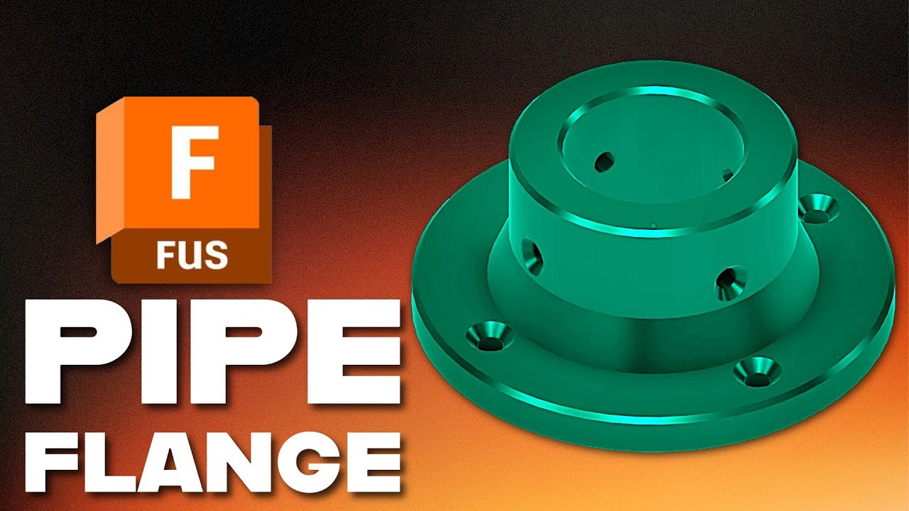
Fusion 360 Parametric PVC Flange Mount (Schedule 40 1 Inch) + Countersunk Holes
Автор: What Make Art
Загружено: 2026-01-24
Просмотров: 594
In this Autodesk Fusion (Fusion 360) tutorial, you’ll learn how to design a strong, parametric 3D printed pipe flange mount for 1 inch Schedule 40 PVC. We start by confirming the nominal outer diameter (1.315 in or 33.4 mm), then build in printer-friendly clearance using user parameters so you can quickly tune the fit for your specific 3D printer. From there, you’ll create the flange base, extrude the sleeve, add countersunk screw holes with the Hole tool, and use circular patterns for clean, repeatable mounting points. Finally, we’ll add chamfers optimized for 3D printing so the part prints flatter and cleaner on the bed.
This workflow is ideal if you want a customizable PVC pipe mount, a 3D printable flange bracket, or a quick Fusion 360 parametric fitting that updates automatically when you change clearance, wall thickness, or flange size.
Chapters
00:00 Overview: 3D printed pipe flange mount for 1 inch Schedule 40 PVC
00:20 Confirm pipe OD in mm and measure with calipers
00:33 Add clearance for a better printed fit
00:46 Sketch the pipe circle and create an offset
01:00 Create a user parameter for clearance (parametric setup)
01:25 Set wall thickness using offsets (example: 10 mm + clearance)
01:47 Draw the flange base circle (around 90 mm)
01:58 Extrude the base (example: 8 mm)
02:19 Extrude the sleeve from the top face (example height: 40 mm)
03:06 Sketch hole placement on the flange base
04:04 Countersunk holes with the Hole tool + circular pattern
05:26 Build a tangent plane and sketch side mounting holes
06:10 Tune side hole sizing/depth and pattern the feature
07:17 Add chamfers for printability and strength
08:42 Ready to 3D print the PVC pipe fitting mount
Key dimensions used in the tutorial (easy to adapt)
PVC OD reference: 33.4 mm (nominal for 1 inch Schedule 40)
Clearance parameter example: 0.2 mm (adjust for your printer)
Wall thickness example: 10 mm + clearance
Flange diameter example: 90 mm
Base thickness example: 8 mm
Sleeve height example: 40 mm
Countersunk hole sizing example (#8): ~9.2 mm head clearance, ~5 mm through clearance
Side hole sizing example (#6): ~7.8 mm head reference, ~4.5 mm clearance, ~12 mm depth
Доступные форматы для скачивания:
Скачать видео mp4
-
Информация по загрузке: