Autocad Civil 3D - Skewed Box Culvert - Verevli Kutu Menfez
Автор: Civil 3D
Загружено: 2023-09-01
Просмотров: 17482
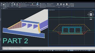
Create skewed box culvert with assembly and its calculation.
Tip kesit ile verevli kutu menfez çizimi ve hesaplarının yapılması.
Contact for assembly: [email protected]
Multi Cell Box Culvert Part 1: • Autocad Civil 3D - Multi Cell Box Culvert ...
Multi Cell Box Culvert Part 2: • Autocad Civil 3D - Multi Cell Box Culvert ...
Limitless Cell Box Culvert: • Limitless Cell Box Culvert
Pipe Culvert: • Autocad Civil 3D - Pipe Culvert - Boru (Bü...
Linkedin Account:
/ civil-3d-designer-76a248299
*It was not possible to create a 3D Solid model properly in the transition areas of the skewed box culvert corridor, so this process was not performed in the video.
*Verevli menfez koridorunun geçiş bölgelerinde düzgün bir şekilde 3D Solid model oluşturulamadığı için videoda bu işlem yapılmamıştır.
OPERATIONAL STEPS
Objective: To draw and perform calculations for a skewed box culvert project for a road project.
*It should be noted that detailed projects for the culvert are required for precise calculations.
The horizontal alignment, vertical profile, cross-section, and corridor for the main road have already been drawn in the project.
Similarly, the horizontal alignment and vertical profile (flow elevation) for the culvert have been previously drawn.
1. Draw the outer boundary of the culvert body. These lines will later serve as targets for the culvert body corridor (target lines should be polylines and not joined).
Draw vertical lines for the wings. These lines will later be defined as the horizontal alignment of the wings.
2. Create the horizontal alignments for the wings. The vertical profiles of these alignments will be transferred from an auxiliary corridor surface that follows the flow elevation of the culvert. This way, the vertical profiles of the body and wings will align with each other.
3. Create cross-sections for the culvert and input the parameters as per the project.
4. Create a corridor for the culvert body (the body corridor will be created after the outer boundaries have been targeted).
Add wing corridors with different horizontal alignments to the body corridor.
5. Create the sloped excavation surface for the culvert, draw cross-sections, and perform excavation volume calculations.
6. Generate application points for the lower boundary of the grout.

Доступные форматы для скачивания:
Скачать видео mp4
-
Информация по загрузке: